

Optimizing Operations with Pneumatic Systems and Automation
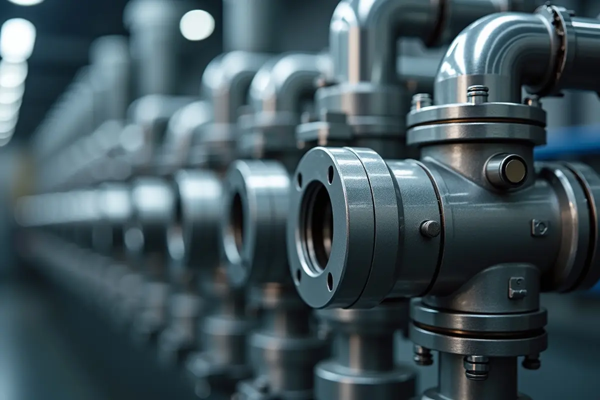
In the rapidly evolving landscape of industrial automation, precision and efficiency are paramount. Achieving these goals often relies on robust and reliable motion control systems. Among the most widely adopted solutions are air pneumatic cylinders, mechanical devices that convert compressed air into linear force and movement.
These versatile actuators play a critical role in manufacturing, packaging, material handling, and countless other applications. Their ability to deliver powerful, clean, and rapid motion makes them an essential component in modern industrial processes.
This article will serve as a comprehensive guide to understanding air pneumatic cylinders and their integration into automated systems. We will explore their fundamental operating principles, examine the diverse range of available types, discuss key specifications for selection, and cover essential considerations for their safe and effective deployment. By the end, you will have a clearer picture of how to leverage pneumatic technology to optimize your operations.
Fundamentals of Pneumatic Systems and Automation
Pneumatic systems harness the power of compressed gas, typically air, to perform mechanical work. This form of fluid power is characterized by its ability to generate linear or rotary motion with high speed and force, making it a cornerstone of modern industrial automation. The appeal of pneumatics lies not only in its operational capabilities but also in its inherent advantages such as clean operation, rapid cycle speed, and a favorable total cost of ownership. Understanding these foundational aspects is crucial for anyone looking to implement or optimize automated processes.
Here is the information organized into a clear Markdown table:
| Actuator Type | Power Source | Typical Applications | Key Advantages | Key Disadvantages |
| Pneumatic | Compressed Air | Assembly, packaging, pick-and-place, clamping | Clean, fast, safe, simple, low cost | Compressibility, lower force/precision than hydro |
| Hydraulic | Pressurized Fluid | Heavy lifting, pressing, high-force applications | High force, rigid, precise force control | Messy, high maintenance, fire hazard, complex |
| Electromechanical | Electricity | Robotics, CNC, precise positioning, variable speed | High precision, programmable, energy efficient | Complex controls, higher initial cost, slower response |
At its heart, a pneumatic system operates on the principle of converting the potential energy of compressed gas into kinetic energy to produce mechanical motion. Air, readily available and non-hazardous, is compressed by an air compressor and stored in a receiver tank. This compressed air is then directed through a network of pipes and hoses to various pneumatic components, including cylinders. When this pressurized air is introduced into a cylinder, it creates a pressure differential across a piston, driving the piston rod to extend or retract.
The operating medium, air, requires careful preparation to ensure the longevity and efficiency of the system. Contaminants such as moisture, oil aerosols, and particulate matter can significantly degrade performance and lead to premature component failure. Therefore, air preparation units, commonly referred to as FRLs (Filter, Regulator, Lubricator), are essential. Filters, in particular, play a critical role, with fine filtration down to 25µm being a common industry requirement. This level of filtration removes most harmful particles, protecting the delicate internal mechanisms of pneumatic cylinders and valves. Without proper air preparation, seals can wear out quickly, valves can clog, and overall system reliability suffers.
Pneumatics vs. Hydraulic and Electromechanical Systems
When selecting an actuator for an industrial application, engineers often weigh the benefits of pneumatic, hydraulic, and electromechanical systems. Each has its distinct advantages, but pneumatics stands out in several key areas, particularly in modern manufacturing environments.
One of the most significant advantages of pneumatics is its inherent cleanliness. Unlike hydraulic systems, which use oil as their operating fluid, pneumatic systems use air. This means there is zero contamination risk from fluid leaks, making pneumatics ideal for applications in cleanroom environments, food processing, pharmaceutical manufacturing, and other industries where product purity is paramount. The absence of oil also eliminates potential fire hazards associated with hydraulic fluids, contributing to a safer working environment.
Pneumatic actuators are also renowned for their high actuation speed. The low viscosity of air allows for very rapid piston movement, enabling quick cycle times in automated processes. While electromechanical systems can offer precise positioning, they often cannot match the sheer speed and responsiveness of pneumatic cylinders for simple linear motion tasks.
Furthermore, pneumatic systems generally boast a favorable power-to-weight ratio, especially in smaller to medium-sized applications, meaning they can deliver significant force from relatively compact and lightweight components. Their design simplicity also translates to easier maintenance and troubleshooting compared to the often more complex hydraulic or electromechanical counterparts. This combination of speed, cleanliness, and ease of maintenance often makes pneumatics the preferred choice for a wide array of automation tasks.
Actuator Technologies and Cylinder Configurations
Pneumatic cylinders are the workhorses of linear motion in automated systems, converting compressed air into mechanical force. Their design varies significantly to meet diverse application requirements, characterized by factors such as bore diameter, stroke length, operating pressure, and temperature ranges. Selecting the appropriate cylinder configuration is critical for optimizing performance, ensuring longevity, and achieving the desired motion control.
Linear Actuator Types and ISO Standards
The most fundamental distinction among pneumatic cylinders is their action: single-acting or double-acting. Single-acting cylinders feature one port for compressed air to enter, which extends the piston rod. Retraction is typically achieved by an internal spring or an external force. These are suitable for applications requiring force in only one direction, such as clamping or ejecting. Double-acting cylinders, conversely, have two ports, allowing compressed air to power both the extension and retraction strokes. This provides controlled force in both directions and offers greater versatility for tasks like pushing and pulling. Double-acting cylinders are not limited by stroke length in the same way spring-return single-acting cylinders are, making them suitable for longer travel distances.
Standardization plays a crucial role in the interoperability and availability of pneumatic components. Several International Organization for Standardization (ISO) standards define the dimensions, mounting interfaces, and performance characteristics of pneumatic cylinders. Key standards include:
- ISO 6432: This standard specifies dimensions for compact cylinders, often referred to as “mini cylinders,” typically with bore sizes ranging from 8 mm to 25 mm. These are ideal for applications where space is limited and lower forces are required.
- ISO 15552: This standard covers cylinders with removable mountings, generally larger bore sizes (32 mm to 320 mm), and is widely adopted for general industrial applications. Cylinders compliant with ISO 15552 often feature tie-rod construction or profile barrels, offering robust performance and interchangeability.
- ISO 21287: This standard defines compact cylinders with smaller overall dimensions than ISO 15552 cylinders but still offers a wider range of bore sizes (e.g., 20 mm to 100 mm) than ISO 6432. They are excellent for space-saving designs that still require significant force.
Many standard cylinders, such as those in the DNC series (ISO 6431, which is often superseded by ISO 15552 in modern contexts), are available in bore sizes from 32 mm to 125 mm and strokes up to 2000 mm. Manufacturers like AIRTEC offer piston rod cylinders with diameters ranging from 6 mm to 320 mm, ensuring compliance with ISO 15552, ISO 6432, and ISO 21287 standards. These cylinders typically operate within a working pressure range of 1-10 bar and are designed for working temperatures between -20°C and +80°C, though specialized versions can accommodate more extreme conditions.
Compact, Rodless, and Specialized Actuators
Beyond the standard single and double-acting types, a variety of specialized pneumatic cylinders exist to address unique application challenges.
Compact Mini Cylinders: Designed for tight spaces, these cylinders sacrifice some stroke length for a significantly reduced overall footprint. The MA Series mini pneumatic cylinder, for instance, is available in bore sizes of 16, 20, 25, 32, and 40 mm, with operating speeds up to 800 mm/s and a temperature range of -5°C to 70°C. Similarly, the SJ series mini cylinders offer even smaller bore sizes, from 6 mm to 16 mm, operating at speeds up to 750 mm/s. These are often used in electronic component assembly or small-scale automation.
Rodless Cylinders: These innovative cylinders eliminate the external piston rod, offering a stroke length equivalent to their overall body length. This design is particularly advantageous when the cylinder itself needs to move a load across a long distance without a protruding rod. Rodless cylinders often use magnetic coupling, where a magnetic piston inside the cylinder barrel drives an external carriage, or mechanical coupling, where a slot in the cylinder body is sealed by a band. Early aircraft carrier catapults, for example, employed steam-powered rodless cylinders, demonstrating their capacity for powerful, long-stroke applications.
Telescoping Cylinders: Also known as multi-stage cylinders, these feature multiple nested sleeves that extend sequentially, allowing for a much longer stroke than a conventional cylinder of the same collapsed length. This compact design makes them suitable for applications requiring extended reach in confined spaces, such as lifting platforms or material handling equipment.
Guided Cylinders: These integrate guide rods alongside the piston rod to prevent rotation and provide enhanced stability, particularly useful for applications involving off-center loads or requiring high precision.
Pneumatic cylinders are available in an impressive range of sizes, from miniature 2.5 mm (1/10 in) diameter units used for picking up delicate electronic components, up to massive 400 mm (16 in) diameter cylinders capable of lifting heavy loads, with some custom designs reaching 1,000 mm (39 in) in diameter. The continuous innovation in materials and design ensures that there is a pneumatic cylinder solution for nearly every linear motion requirement in industrial automation.
Engineering Calculations and Component Sizing
Effective deployment of pneumatic cylinders hinges on accurate engineering calculations and meticulous component sizing. This involves understanding the relationship between supply pressure, effective area, and the theoretical force generated. Furthermore, factors like rod diameter, mechanical efficiency, load dynamics, and potential buckling limits must be carefully considered to ensure the cylinder performs reliably and safely within its intended application.
Force Calculations for Instroke and Outstroke
Calculating the force output of a pneumatic cylinder is fundamental to selecting the correct size for a given application. The basic principle is that force is a product of pressure and the effective area upon which that pressure acts.
For the outstroke (extension) of a double-acting cylinder, the compressed air acts on the entire surface area of the piston. The formula for theoretical outstroke force (F_out) is: F_out = P × A_piston Where:
Pis the supply pressure (e.g., in psi or bar).A_pistonis the cross-sectional area of the piston (π * (bore diameter/2)^2).
For the instroke (retraction) of a double-acting cylinder, the compressed air acts on the piston’s surface area minus the cross-sectional area of the piston rod. This reduced area is often referred to as the annulus area. The formula for theoretical instroke force (F_in) is: F_in = P × (A_piston - A_rod) Where:
Pis the supply pressure.A_pistonis the cross-sectional area of the piston.A_rodis the cross-sectional area of the piston rod (π * (rod diameter/2)^2).
These calculations yield theoretical forces. In real-world applications, several factors reduce the actual usable force. These include:
- Friction Loss: Internal friction from seals and bearings.
- Pressure Differential: Pressure drops across valves and hoses.
- Acceleration Forces: The force required to accelerate the mass of the piston, rod, and attached load.
- Mechanical Efficiency: The overall efficiency of the system, typically around 80-90% for well-maintained pneumatic cylinders.
Therefore, it’s common practice to apply a safety factor, often 1.5 to 2 times the calculated theoretical force, to ensure the cylinder has sufficient power to overcome all operational resistances and perform reliably.
Sizing Guidelines for Pneumatic Systems and Automation
Proper sizing of pneumatic cylinders goes beyond just force calculation; it involves a holistic view of the application’s requirements. Key considerations include:
Bore Size and Stroke Length: These are the primary determinants of a cylinder’s force output and range of motion. Bore sizes can range significantly, with standard cylinders like the SC/SU series offering bore sizes from 32 mm to 200 mm. Stroke lengths can vary from a few millimeters to several meters, depending on the cylinder type. For instance, the MAL series mini cylinders, with bore sizes from 16 mm to 40 mm, are often used for shorter strokes.
Operating Speed: The required speed of the application dictates air flow requirements and can influence cylinder selection. Many standard cylinders, such as the SC/SU and MAL series, offer operating speed ranges from 50-800 mm/s. Achieving higher speeds often requires larger port sizes, quick-exhaust valves, and careful consideration of air supply.
Working Pressure Margin: While a cylinder might be rated for a maximum pressure, operating it consistently at or near this limit can reduce its lifespan. It’s advisable to select a cylinder with a working pressure margin, ensuring the system operates comfortably below the maximum rated pressure. The SI series, for example, has a working pressure range of 1-9.0 bar but a guaranteed pressure of 13.5 bar, providing a healthy margin.
Rod Stress Analysis and Buckling Limits: For cylinders with long strokes or those subjected to significant compressive loads, the piston rod can be prone to buckling. Engineers must calculate the critical buckling load based on the rod’s material, diameter, and unsupported length, ensuring it exceeds the maximum anticipated compressive force. Manufacturers provide guidelines and charts for these calculations.
Air Consumption: Understanding the air consumption of a cylinder is vital for sizing the compressor and air preparation system. Air consumption depends on the cylinder’s bore, stroke, operating pressure, and cycle rate. Overlooking this can lead to insufficient air supply and reduced system performance.
When sourcing components, it is often beneficial to consult with a knowledgeable and reputable pneumatic component supplier. A trusted provider of pneumatic solutions can offer expert advice on product selection, ensuring compatibility and optimal performance for your specific application. For a comprehensive range of pneumatic products and expert support, consider exploring options from a dedicated pneumatic systems distributor.
Integration, Safety, and Control Mechanisms
The effectiveness of pneumatic cylinders in automation is heavily reliant on their seamless integration with control systems and the implementation of robust safety features. This section explores the critical components and strategies that ensure precise motion control, protect equipment, and safeguard personnel.
Cushioning, Position Sensing, and Fail-Safe Features
To manage the kinetic energy of a moving piston and prevent damage from impact at the end of its stroke, pneumatic cylinders often incorporate cushioning mechanisms. These can be fixed or adjustable. Fixed cushions provide a consistent damping effect, while adjustable cushions allow for fine-tuning of deceleration, which can be critical for optimizing cycle times and preventing shock. Using cushion end cylinders is a best practice to avoid impact damage, especially during rapid retraction or extension.
Position sensing is crucial for feedback and control in automated systems. Magnetic switches, such as reed switches or solid-state sensors, are commonly used. These sensors detect the presence of a magnet embedded in the piston, signaling its position (e.g., fully extended or fully retracted) to the control system. This enables precise sequencing of operations and contributes to overall system accuracy.
Fail-safe features are designed to ensure safety in the event of power loss or system malfunction. For instance, single-acting cylinders with spring return mechanisms are inherently fail-safe in one direction, returning to a home position when air pressure is removed.
Lock-up valves can be employed to hold a cylinder in position, preventing movement if the air supply fails. In environments with potentially explosive atmospheres, cylinders with ATEX certification are mandatory, ensuring they are designed and constructed to prevent ignition. Pneumatic cylinders are often preferred in clean environments because gas leaks do not contaminate surroundings, which is a significant safety and operational advantage over hydraulic systems.
Air Preparation and Valve Control Architecture
The longevity and reliable operation of any pneumatic system begin with proper air preparation. This typically involves a Filter-Regulator-Lubricator (FRL) unit. The filter removes contaminants (as discussed, 25µm filtration is common), the regulator maintains a consistent operating pressure, and the lubricator (if used) adds a fine mist of oil to the air to reduce friction and wear on internal components, though many modern cylinders are designed for non-lubricated operation. It’s essential to match the working pressure range of the FRL unit to the cylinder’s specifications and to check temperature limits before installation to prevent premature failure.
Directional control valves are the brains of the pneumatic system, directing the flow of compressed air to the cylinders. These valves come in various configurations (e.g., 2/2-way, 3/2-way, 5/2-way) and actuation methods (manual, mechanical, solenoid-operated). The choice of valve depends on the required motion pattern and control complexity. Proportional regulators offer more sophisticated control, allowing for variable pressure output and thus variable force or speed, rather than just on/off control.
Port sizes on cylinders and valves (ranging from M5x0.8 for mini cylinders to G3/8 or larger for industrial applications) must be correctly matched to ensure adequate airflow and prevent pressure drops that could hinder performance. Flow controls are often installed in the exhaust lines of cylinders to precisely regulate the piston speed. Quick-exhaust valves can be used to rapidly vent air from a cylinder chamber, significantly increasing retraction or extension speeds and optimizing cycle times. Ensuring proper sealing throughout the system is also paramount to minimize air leakage and maintain consistent pressure, contributing to both efficiency and reliability.
Frequently Asked Questions About Pneumatic Systems
Understanding the nuances of pneumatic systems can lead to more efficient and reliable automation. Here, we address some common questions regarding their operation, selection, and performance.
What are the main advantages of pneumatic actuators in clean environments?
Pneumatic actuators offer distinct advantages in clean environments due to their reliance on compressed air as the operating medium. Firstly, they provide oil-free operation, which means there is no risk of fluid leaks that could contaminate products or processes. This is critical in industries such as food processing, pharmaceuticals, and semiconductor manufacturing, where strict hygiene and purity standards must be maintained. Unlike hydraulic systems, which can be messy and require careful handling of hydraulic fluids, pneumatic systems are inherently cleaner.
Secondly, the absence of fluid leaks means zero fluid leak contamination of the surrounding environment. This not only protects the product but also simplifies cleanup and reduces maintenance. Engineers often prefer pneumatics because they are quieter, cleaner, and require less space for fluid storage compared to hydraulics. This makes them highly suitable for cleanroom compliance, where even microscopic particles or chemical residues can compromise the manufacturing process. The ability to operate safely and cleanly without introducing contaminants is a primary reason for their widespread adoption in sensitive applications.
How do single-acting and double-acting pneumatic cylinders differ in operation?
The fundamental difference between single-acting and double-acting pneumatic cylinders lies in their method of actuation and force application:
- Single-acting cylinders have only one port for compressed air. When air enters this port, it extends the piston rod. The return stroke is achieved by an internal spring or an external force (e.g., gravity or the load itself) once the air pressure is released. This means they provide powered motion in only one direction. They are ideal for applications like clamping, ejecting, or simple lifting where a controlled return stroke is not critical, or where the return force is minimal. Their stroke length is typically limited by the spring’s compression range.
- Double-acting cylinders, in contrast, feature two ports, one at each end of the cylinder barrel. Compressed air can be directed to either port, allowing for powered motion and controlled force in both the extension (outstroke) and retraction (instroke) directions. This provides greater versatility, enabling bi-directional force output for tasks like pushing and pulling, or precise positioning. Since both strokes are powered by air, their stroke versatility is much greater, and they are not limited by spring length, allowing for significantly longer travel distances.
How is effective force determined for extending and retracting strokes?
The effective force generated by a pneumatic cylinder is determined by the system air pressure acting on the piston’s surface area. However, this calculation differs slightly for the extending (outstroke) and retracting (instroke) movements due to the presence of the piston rod.
For the extending stroke, the compressed air pushes against the entire bore surface area of the piston. The formula is straightforward: Force = Pressure × Piston Area. This typically results in the maximum force output of the cylinder.
For the retracting stroke, the compressed air pushes against the piston, but the rod cross-sectional area must be subtracted from the total piston area. This reduced area, often called the annulus area, is the effective surface upon which the pressure acts. Therefore, the retracting force is always less than the extending force. The formula becomes: Force = Pressure × (Piston Area – Rod Area).
It is crucial to account for the system air pressure available at the cylinder, as pressure drops can occur across supply lines and valves. Furthermore, a mechanical efficiency factor (typically 0.8 to 0.9) should be applied to these theoretical calculations to account for friction from seals and bearings, providing a more realistic estimate of the actual usable force. This careful consideration ensures that the selected cylinder can reliably perform the required work in both directions.
Conclusion
As we navigate the complexities of industrial automation in September 2026, the role of air pneumatic cylinders remains as vital as ever. From their fundamental principles of converting compressed air into linear motion to the diverse array of types and configurations, pneumatic systems offer a compelling solution for a vast range of applications. Their inherent advantages in cleanliness, speed, and ease of maintenance position them as a preferred choice over hydraulics or electromechanical systems in many contexts, particularly where environmental purity is paramount.
Understanding the key specifications for selection, mastering force calculation for both outstroke and instroke, and appreciating the importance of proper air preparation and control mechanisms are all critical steps towards optimizing operations. Whether it’s the compact efficiency of mini cylinders, the extended reach of telescoping designs, or the robust performance of ISO-standardized units, there is a pneumatic solution tailored for virtually every industrial need. By integrating these insights, engineers and system designers can make informed decisions, ensuring the safe, efficient, and future-proof deployment of pneumatic technology in their automation endeavors.





0